Driving a car owned by the firm I work, I had the choice of using a magnetic antenna or finding an other solution. A magnetic antenna has the risk of being removed somewhere so I started looking for the other solution. In a VHF Communications of spring 1978 I found a project of an antenna splitter designed by DK1OF. The Idea is to use a 2mtr. mobile antenna with a 2 mtr. transceiver and a broadcast radio.
I could use the hole of the standard broadcast antenna to mount a 2 mtr. 1/4 lambda antenna, so this was the way to go.
Not only the schematics where described but also the theory and the formula's to compute the components. This made it possible to recalculate the whole thing for my proper use. The original concept used as center frequency of 95 MHz for the FM-Broadcast there where I use to listen to stations centered around 91 MHz. As a center frequency for 2 mtr. I used 145MHz.
The Schema
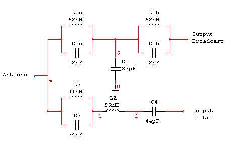
The Formula's: ,,,,,,
R = Input impedance = Output impedance = (50 Ω)
F1 = Cut-Off frequency Broadcast (91 MHz)
F2 = Center Frequency off 2 mtr. (145 MHz)
 |
 |
| |
|
| The calculations are automated in an Excel worksheet you can download with the rest of the project files: Antenna Splitter.zip |
The results:
| Calculated | used | |
| L1a = L1b = | 5,167619E-08 | 2,5-Turns |
| L2= | 5,488101E-08 | 2,5-Turns |
| L3= | 4,072309E-08 | 2 Turns |
| Coils wounded on a 6 mm coil former with 1 mm Silver plated copper wire. The coil-formers are provided with a VHF usable core | ||
| C1a = C1b = | 2,331384E-11 | 22pF |
| C2= | 3,459890E-11 | 33pF |
| C3= | 7,348927E-11 | 27pF + 47pF |
| C4= | 4,390481E-11 | 22pF + 22pF |
The theoretical frequency response:
1) The response from the antenna to the 2 Mtr. Transceiver:
| The center frequency (91 MHz) of the FM Broadcast cut-of is more then 40 db and on 145 MHz the attenuation is quasi 0 db. the 2 meter harmonics are extra attenuated even so the frequency range of the MW and LW Broadcast. | 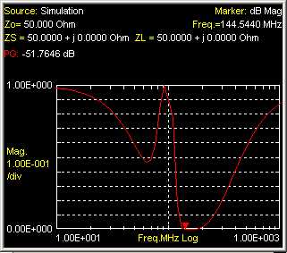 |
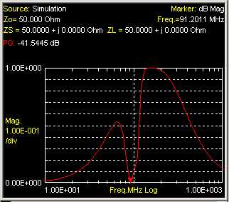
2) The response from the antenna to the Broadcast radio:
| Here the 2 meter frequency is suppressed more than 50 db, the FM-Broadcast and the MW and LW are nearly not attenuated.
The impedances are all 50 Ω - (look out for the broadcast radio, eventually one has to match the input impedance.) |
 |
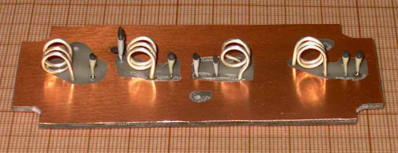
The next step is to work-out the project in a practical way.
Parts:

- For mechanical strong ness, a car can trill and shake a lot, I use a commercial die-cast box from 100mm x 50mm.
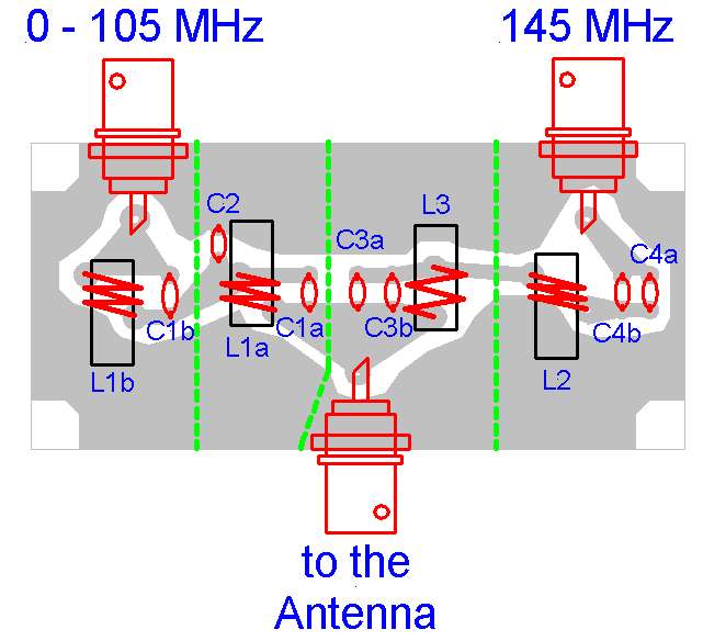
- 3 x 1-Hole mountable BNC connectors
- 4 x VHF Coil cores with adjustable core (it is more stable for car-use to adjust the coils then adjusting capacitors)
- 1mm diameter - Silver coated - wire
- 4 x 22pf
- 1 x 33pF
- 1 x 27pF
- 1 x 47pF
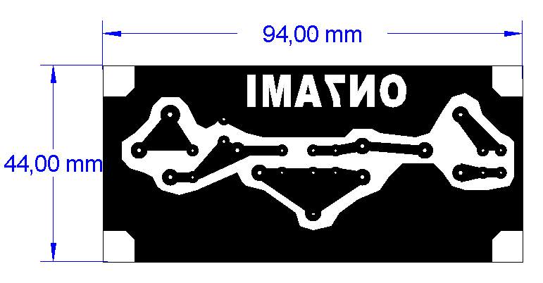
Design of a printed circuit:
Solder-side seen from components
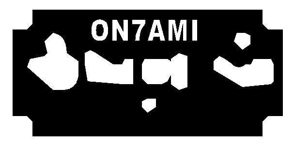
Earth-mask on the component side
Position of the components:
Lično zapažanje:
Ovaj spliter sam 2010. godine sagradio i koristim ga u terencu Nivi. Antena je 5/8-ka i veoma dobro se pokazala i kao prijemna FM auto radio-antena. Nisam imao priliku da spliter podešavam na spektro analajzeru, ali uz pomoć signal generatora sam ga uspješno podesio. TX emisija sa snagom od 45w na 145 Mhz nema uticaj na prijem radio-difuzije.
Zoran, E73S